Download Free Latest Software
Allegro pcb design software crack download
Allegro PCB Design Software is a powerful and widely-used electronic design automation (EDA) tool that enables engineers and designers to create complex printed circuit boards (PCBs) with precision and efficiency.
Overview
This comprehensive software suite offers a wide range of features and capabilities that make it an indispensable tool for professionals in the electronics industry.
The software provides a robust and user-friendly interface that simplifies the PCB design process, allowing users to quickly and accurately create, simulate, and optimize their designs. With its advanced features and intuitive tools, Allegro PCB Design Software has become a go-to solution for many leading electronics companies and design teams around the world.
Key Features and Capabilities
- Schematic Capture: The software’s intuitive schematic capture feature allows users to easily create and edit electronic schematics, ensuring that their design concepts are accurately represented.
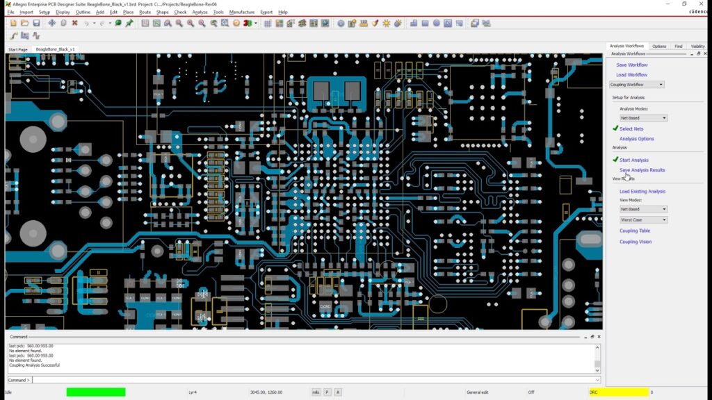
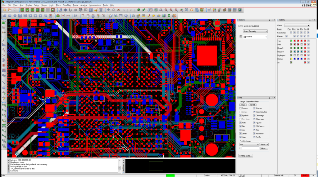
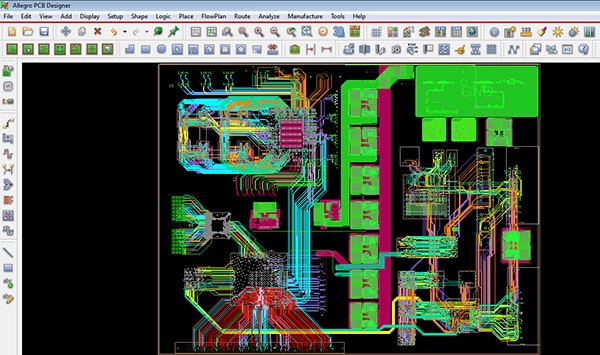
- PCB Layout: Allegro’s powerful PCB layout tools enable users to effortlessly design and optimize their circuit board layouts, ensuring optimal component placement, routing, and connectivity.
- Signal Integrity Analysis: The software’s integrated signal integrity analysis tools help designers identify and address potential issues in their designs, ensuring signal quality and reliability.
- Thermal Analysis: Allegro’s thermal analysis capabilities allow users to simulate and analyze the thermal characteristics of their PCB designs, ensuring that components and circuitry are operating within their thermal limits.
- Manufacturing Support: The software provides comprehensive support for manufacturing processes, including generating industry-standard design files and facilitating seamless communication with manufacturing partners.
Technical Specifications
Version: Allegro PCB Design Software 17.4
Interface Language: English
Audio Language: N/A
Uploader / Repacker Group: Cadence Design Systems
File Name: Allegro_PCB_Design_Software_17.4.exe
Download Size: 2.8 GB
System Requirements
Operating System: Windows 10/11 (64-bit)
Processor: Intel Core i5 or equivalent
RAM: 8 GB or more
Storage: 10 GB of available disk space
Graphics: DirectX 11 compatible graphics card
Adjusting Graphics Settings
- Open the Allegro PCB Design Software and go to the “Options” menu.
- Select “System Settings” and then navigate to the “Graphics” tab.
- Adjust the graphics settings according to your system’s capabilities, such as resolution, color depth, and hardware acceleration.
- Save the changes and restart the software to apply the new settings.
Troubleshooting Common Issues
- Installation Problems: If you encounter any issues during the installation process, ensure that your system meets the minimum requirements and try running the installer as an administrator.
- Compatibility Errors: If you experience compatibility issues with the software, try updating your operating system, graphics drivers, or other critical system components.
- Performance Issues: If the software is running slowly or experiencing performance problems, try adjusting the graphics settings or closing other resource-intensive applications running in the background.
- Licensing Errors: If you encounter any issues with the software’s licensing, contact the Cadence Design Systems support team for assistance.
How to Download and Install
- Visit the official Cadence Design Systems website and locate the download page for Allegro PCB Design Software 17.4.
- Click the “Download” button and follow the on-screen instructions to save the installer file to your local machine.
- Once the download is complete, double-click the installer file to begin the installation process.
- Follow the on-screen prompts to complete the installation, making sure to select the appropriate installation options for your needs.
How to Use Allegro PCB Design Software
- Launch the Allegro PCB Design Software from your desktop or start menu.
- Start a new project or open an existing design file.
- Use the various design tools and features to create, edit, and optimize your PCB layout.
- Utilize the analysis tools to ensure signal integrity, thermal management, and manufacturing compliance.
- Generate the necessary design files and export them for manufacturing or further collaboration.
For more information, you can visit the following websites:
Frezsa, Qruma, Mrafb, Deffrent, Toreef, Gulvezir, Flex44d, and AACPI. Each site offers unique resources and insights, so feel free to explore them to find the information you need.

Leave a Reply